
THREADED INSERTS
More Strength.
Less Wear.
Permanent, wear-resistant internal threads anchor fasteners in metal, plastic, wood, or composites. Groov-Pin’s Threaded Inserts strengthen assemblies and increase load-bearing capacity.
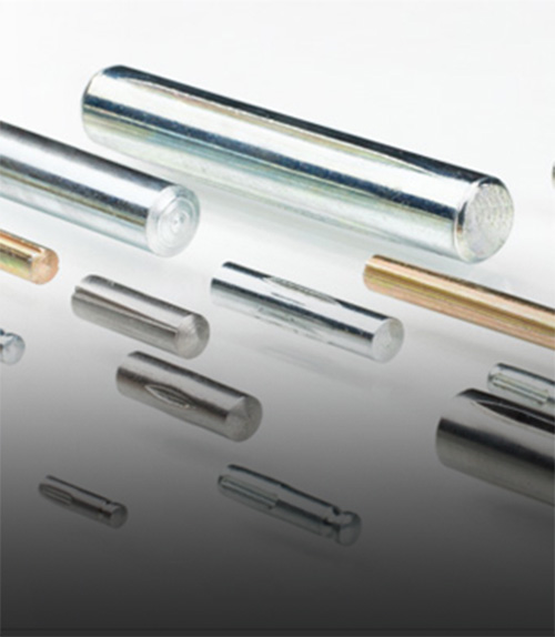
GROOVED PINS
Superior Hold.
Shock Resistant.
Used in the automotive and aerospace industries, cylindrical Grooved Pins feature three longitudinal grooves that precisely expand the pin’s original diameter. This creates a superior spring mechanism and holding power.

PRECISION TURNED COMPONENTS
Precise Performance.
Design Flexibility.
Brass and stainless steel Precision Turned Components meet critical tolerance and finish requirements demanded by many industries including telecommunications, automotive, medical, aerospace, and irrigation.
Industries

Aerospace

Energy

Medical

Defense & Law
Enforcement

Farming &
Irrigation
Aerospace
Energy
Medical
Defense & Law
Enforcement
Farming &
Irrigation

Telecommunications
Aerospace
Energy
Medical
Defense & Law
Enforcement
Farming &
Irrigation
Telecommunications
Telecommunications

Die Casters

Distribution

Automotive
Die Casters
Distribution
Automotive
Die Casters
Distribution
Automotive

COMPANY CULTURE
Since 1926, Groov-Pin’s skilled and dedicated employees have been committed to delivering fasteners of the highest quality. Through business acquisitions, and product and technological advancements, Groov-Pin has been able to expand its markets, provide stronger products to its customers, and allow employees to work more efficiently.
One of Groov-Pin’s most effective changes has been the adoption of lean manufacturing. Some of the employee-driven lean developments helped Groov-Pin retain its competitive advantage, even through trying economic times.
Groov-Pin is also dedicated to the continuous improvement of its employee wellness program. Groov-Pin has been recognized as a Healthiest Employer in Rhode Island for the past three years. The award-winning wellness program, called GP Fit, encourages employees to prioritize their physical, mental, and financial health.
Knowledge Base of Videos
Where can you use Groov-Pin fasteners? The possibilities are endless. Groov-Pin’s Tap-Lok Threaded Inserts, Speedserts, solid Grooved Pins, and Precision Turned Components are designed for simple, economical installation.
Learn how easy it is to install our Threaded Inserts, which are also compatible with automatic installation methods. Just one step provides permanent, reinforced threads in metal, plastic, cast, or molded parts. Since they cover the spectrum of installation methods, Groov-Pin inserts are widely chosen by OEMs for medium- and high-volume production.
How to Install Threaded Inserts Using a Flex Arm
Sed ut perspiciatis unde omnis iste natus error sit voluptatem accusantium dolorem laudantium, totam rem aperiam, eaque ipsa quae ab illo inventore veritatis et quasi architecto beatae vitae dicta sunt explicabo. Nemo enim ipsam voluptatem quia.
Neque porro quisquam est, qui dolorem ipsum quia dolor sit amet, consectetur, adipisci velit, sed quia non numquam eius modi tempora incidunt ut labore et dolore magnam aliquam quaerat voluptatem. Ut enim ad minima veniam, quis nostrum exercitationem ullam corporis suscipit laboriosam, nisi ut aliquid.